
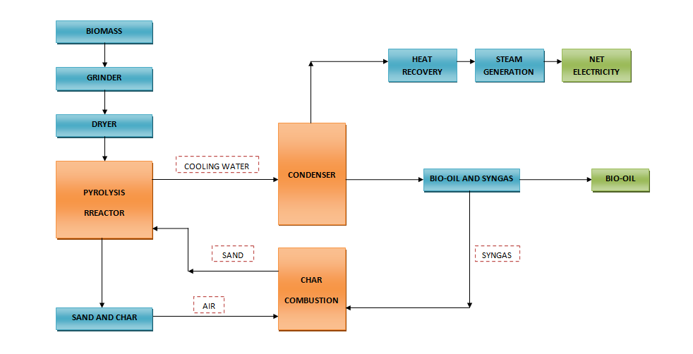
Block Diagram for Fast Pyrolysis System
| block_diagram.pdf |
- Biomass particles are fed to the pyrolysis reactor together with an excess flow of sand, which acts as circulating heat carrier material.
- The biomass and sand are mixed within the pyrolysis reactor and converted into pyrolysis oil vapors, gas and char.
- The produced vapours and gasses pass through several cyclones before entering the condenser, in which the vapours are quenched by re-circulated oil.
- The sand and char are transported to a combustor, where air is added to combust the char and reheat the sand.
- The hot sand is then transported back to the reactor to close the loop.
This system ensures that the excess heat which is produced by the combustion of pyrolysis char and non-condensable gases is captured as steam so it can be utilized in for example a steam turbine system. Some steam will be used for electric power generation and feedstock drying but the excess steam can be sold to a nearby industrial site or district heating grid.
Process Flow Diagram (PFD) for Fast Pyrolysis System
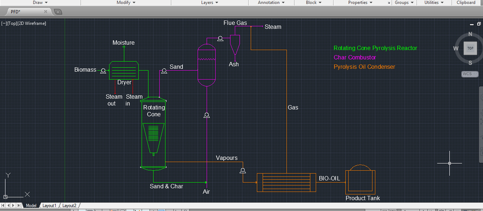
| pfd.dwg |
